Crib wall– a retaining wall (that holds up a trail, path, or road, or one that uses wood or concrete cribbing)
Retaining wall– a wall that holds/retains material, including the backslope above a trail, path, or road
A need for walling?
Walls might be required to:
- bring grades to a desired percentage
- assist with switchbacks for #1 and possibly #3
- keep people on a trail or to cut down on short cutting
- hold a trail or or backslope with poor slope stability, which complicates walling on those same slopes
- retain surfacing materials
-A Word on Wall Batter-
I don’t know that there is a crib wall “authority.” There certainly are a lot opinions and “styles” among laypeople, not to mention numbers crunched by engineers. Forgetting style, I’ll put my money with numbers and engineers, and techniques to ‘fight’ lateral earth pressure.
That said, who do I believe, or better, where should I place faith…in the Forest Service (here, and below), or the Dry Stone Conservancy (DSC video ) and Stone Trust (ST pdf and page)?
I place more trust in the Forest Service’s techniques, because what the DSC and ST are advocating is the construction of a free standing wall as a retaining wall as seen in the literature, images, and video linked above. The DSC video says, “keep courses perfectly horizontal,” no wall batter, only face batter (at 6:1 or 5:1). The ST advocates the same thing. I’d call off-setting with face batter alone a “false batter,” whereas “true” face batter is the result of, or reflection of, an insloped course batter. Insloped courses will cause the face to have a batter naturally, as the face batter will mirror the inslope as the course and face angles are congruent. This isn’t to say there is no advantage with face batter alone and horizontal courses vs. horizontal courses and vertical walls, but neither can compete with true course batter. Further, it’s not as if a free standing wall can’t retain material, but as seen in the image below, walls with face batter alone are not as strong in the fight against lateral earth pressure.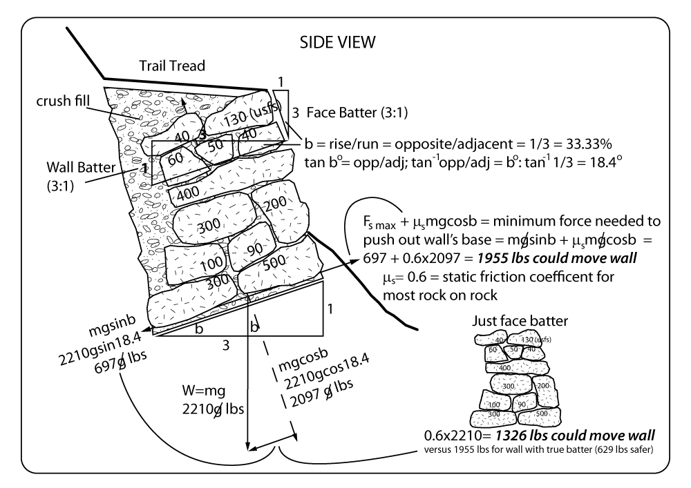
I’ll be posting an extended explanation in the next few months, but here’s a start:^ it’s a little more complicated* than this, but the general principle is there. If it’s known how much material will be contained and/or supported the wall can be customized for lateral earth pressure (see below, and this link on how to determine LEP)
Batters should be…what? Says who? Why?
| Batter Recommendation | Degrees | Force to move 100 lb rock: face batter alone, no course batter |
Force to move 100 lb rock: course batter matches face batter |
% stronger |
| FS, 2:1 | 26.5 | 100 x 0.6 = 60 | 100sin26.5+0.6(100cos26.5) = 97 | 37/60 = 61 |
| FS, 3:1 | 18.4 | 100 x 0.6 = 60 | 100sin18.4+0.6(100cos18.4) = 87 | 27/60 = 45 |
| FS, 4:1 | 14 | 100 x 0.6 = 60 | 100sin14+0.6(100cos14) = 82 | 22/60 = 36 |
| DSC, ST, 5:1 | 11.3 | 100 x 0.6 = 60 | n/a…60 | 0 |
| DSC, ST, 6:1 | 9.5 | 100 x 0.6 = 60 | n/a…60 | 0 |
As seen above, not only do the Stone Trust and and Dry Stone Conservancy want you to use face batter alone, they also want you to use less batter. Is there a structural reason for this, or is it strictly aesthetic? As you can see, having face batter changes nothing in regards to the fight against friction and the forces stopping a stone from sliding out. In that regard, there is no apparent structural function to a false batter (face batter alone). If only face batter is used, and the courses are not battered, then no matter what your face batter is, the result is the same (60 lbs to move a 100 lb stone if the friction coefficient is 0.6…a change in face batter alone changes nothing).
Will face batter help the wall from pushing out anymore than if it was vertical? No, again, only weight and friction are relevant. Perhaps face batter is insurance, buying a few inches in case a wall does start to push out an inch or two on the top tiers…which can begin the road to failure.
Conceptually, I can see believing that face batter alone could provide some leverage, like trying to push someone over standing with both feet together vs. spread apart. This is bad reasoning however, because if someone can remain rigid enough, it will take the SAME force to make them slide across flat ground– feet together or apart– it’s strictly a function of weight and the friction coefficient of the surfaces (a function of the surface irregularities, or “asperities,” and weight). Not even the surface area of their feet matter, just their weight and friction. In other words, someone with much bigger feet and the same shoes on the same surface (if they weigh the same) will take the same force to move as the smaller shoed individual. As seen in the equations above, no course batter results in no advantage, or said differently, if your wall has only face batter the batter don’t matter. There may be some structural function or positive force to having face batter alone, but it remains to be seen. What the laws of nature and physics say appears to be true, and nowhere is surface area a factor (unless weight increases).
The Forest Service recommendations ask you to dig your heels into the ground, like you would cheating in a game of tug-o-war. In conclusion, I trust the Forest Service will conserve a wall against LEP and stand up 0.3 – 0.6 times better than a ST or DSC wall…I’ll take a 30-60% increase in integrity, as to not slide the structure away from its intended function.
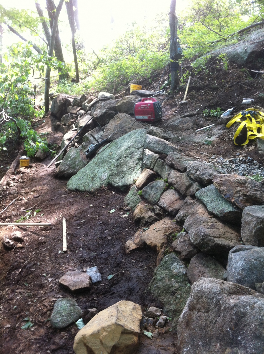
-Minimizing Running Joints- Minimizing running joints is also of great importance for a solid wall. In the image below, there are a few running joints, especially at the tie stone, but in general the joints are broken both horizontally, and vertically. In regards to the last point, some dry wallers do fine when breaking vertical joints, but also important is breaking running horizontal joints. At this point in time I can’t put numbers on how important breaking horizontal joints is to structural integrity (if at all) or how it works. I’ll hypothesize that unbroken joints in any direction are bad, and that breaking both is optimal. Running joints can start a domino effect, where if one stone gets loose or comes out the probability of failure is higher for a neighboring stone if it is in the same planes of a run. This wall (Bear Mtn. NY, AT) has lateral running joints, but its broken by tie stones in the foreground, and below the generator:
The wall below also has running lateral joints, but it appears to have mortar, and may be safe given the built-in curve does break the lateral joint to some degree.
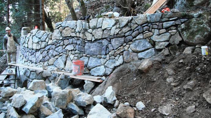
The batter looks to be about 3-4:1 if the worker’s shoulders are at 5 feet and the wall is 1.5 feet away- hard to say. I can’t see how thick the wall is. At six feet high or so, three feet wide would be wise. Hard to say what this wall’s application is…perhaps for a trail given its PTBA source. It is pretty.
http://geotechnicalinfo.com/retaining_walls_technical_guidance.html:
Calculating the Total Lateral Earth Pressure Force
PDF: Earth Pressure and Retaining Wall Basics
Spreadsheet: Lateral-Earth-Pressure
…not intended to be exhaustive nor does it discuss a wide range of surcharge loads or other lateral forces that might also act on a wall
The total lateral earth pressure force is the area of the pressure diagram along the wall. In the example shown later in this course, the area of the earth pressure diagram is the lateral earth pressure at the bottom of the wall Ka γ H (note that γ H is the vertical effective overburden pressure in this example) times the height of the wall (H) times one-half (1/2) since the pressure distribution increases linearly with depth creating a triangular shape.
Thus the total active earth pressure force (Pa) acting along the back of the wall is the area of the pressure diagram expressed as:
Pa = ½ Ka γ H^2
(6.1)
The total passive earth pressure force is:
Pp = ½ Kp γ H^2
(6.2)
The total force acts along the back of the wall at a height of H/3 from the base of the wall. In more complicated cases, the earth pressure distribution diagram is drawn and the total force is calculated by determining the separate areas of the pressure diagram. The location of the resultant force is also determined. The direction of the force is based upon the angle of backfill and in the Coulomb case, it is also based upon the soil-wall friction value.
…it is the active pressure that produces the destabilizing earth force behind retaining walls. Although passive pressures might develop along the toe of the wall and provide resistance, it is commonly ignored…more
Additional cribbing info
Pingback: Dry Stone Jazz | Trailism