Update (2026): The math on this page now lives in a dedicated physics tool, BASE-Bf, built by TrailACT. It computes Equivalent Fall Height landings, G-force-bound clothoid ramps, and three-speed trajectory overlays — and exports DXF blueprints. The conceptual writing below is still relevant background.
The information below will eventually be updated and replaced with the User Manual for the BASE-Bf software at TrailACT.
I don’t hit huge jumps, drops, or gaps, at least not at this point in my life. If things start to get over 5 feet high or more than 20 feet between lip and landing, especially with gaps, I’m probably not going to do it. Regardless, I’ve hit some good jumps and drops that seem to be dead on, take-off to landing that is. I’ve also gone too slow and too fast on jumps and suffered the consequences.
I think a lot of builders go with trial and error: ride it, reshape it, ride it… In other words, experimentation or science. By science I mean the consistency or repetition of outcome, and even prediction, which is what riders seek— science meets mathematics (and art or craft).
The math starts relatively simple for jumps and ladder drops (see below), but a lot depends on the rider, the bike, and how they behave on lift-off, but a little math will get riders/builders in the ballpark faster so there is more science and success, and less trial-and-error witchcraft. Experienced builders that don’t break out calculators are good at witchcraft, or perhaps its craftsmanship/art; they can see the parabolic line of flight when they build because chances are they have enough flight-time to render themselves Pilots in Command. However, chances are their luck has run out more than once, as well as their time riding because they were re/moving dirt, perhaps with elbows, knees, and face.
The likelihood of a rough landing or total miss and serious crash are lowered if a little math is done first. Unless of course you want to move earth multiple times rather than ride. Ride more or build more? Eat shit more? The answer is obvious, do your homework first. You can bet your ass that some stuntmen and record breaking jump events broke out calculators and rulers, and possibly consulted physicists or engineers. If it’s not evident, what have you ridden or built that worked, or that you really liked, did you consider measuring it to recreate it…and is your speed the same? See the PDFs listed near the bottom of this page and the discussions surrounding Equivalent Fall Heights (EFH).
Equivalent Fall Heights
The table and landing ramp should be designed to lower the impact upon landing to a “safe” distance. The goal is to create a landing where the impact is nearly the same or does not surpass the EFH along the entire landing. This usually involves a landing that gets steeper as it gets farther from the knuckle. EFH is typically around a 4-5 feet high maximum in the ski industry. Meaning when someone lands they are effectively landing with an equivalent impact to the designed EFH, whatever that might be (usually under 4.9 ft (1.5 m)). What that should be for bikes I am not sure. It could be higher with suspension, but I can’t say by how much. The important piece would be what could most bodies handle if things go wrong, not what a bike can handle. The safe bet is to stick with the research cited in the PDFs below. EFH considers the kinetic energy of the landing velocity perpendicular the surface divided by mg, EFH = velocity/mg, thus steep farther away where velocities increase. The landing mimics and follows the parabolic flight path to some degree. Landings with an EFH over 4.9 ft are likely to cause most knees to buckle on boards, skis, and bikes.
For a step-by-step guide on actually doing all (or most of) the math and using this calculator and more read the notes below, and see this Jump Building Guide.
Projectile Motion and Newton
The laws of motion determine jump flight. In particular, equations surrounding projectile motion. Realizing the real world applications of these facts of life made me sit up in physics class because at that time bike jumps, skateboard ramps, and golf were a thing for me. On this page I share what I took away from my schooling and homegrown experimentation with jumps, and created a jump calculator (below) to help (and possibly hurt) other people with similar interests. I still use it as a builder, and sometimes as a rider to learn from my experiences.
That said, you can finally feel bad about thinking you would never need math again, which perhaps you don’t because I did some of the homework for you. A little math may send you far and high. It can also lower the amount of “experimentation” and tweaking to get you closer to your desired outcome faster. I can’t say it will lower risks, or lower insurance premiums! In spite of geology and rider behaviors throwing the best intentions a curve-ball, break out rulers and protractors with your shovels…
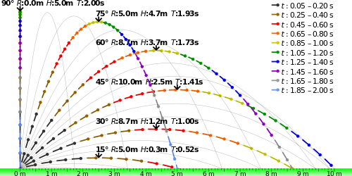
Parabolic Jump/Projectile Trajectories^
Lines of jump flight up and off a ramp or down/off a drop are parabolic. However, with drag forces included the parabola gets distorted or shifted and the flight is not really “projectile motion” as velocity and acceleration are not constant, but constantly changing.
Notice how 30o and 60o (and other angles in light gray) yield the same distance or range, R, with the same initial velocity, but yield significantly different heights. A 45o angle will give the farthest range– it’s not magic, it’s the Law. Try 30o and 60o degrees using the calculator below to see for yourself, or experiment by building two ramps side-by-side at the same height and sharing the same landing area (the 60o landing side should be a little steeper though, or go between 30o and 60o for both, perhaps 45o. There is more on angles below.). (See the Excel sheet image for a tabular representation of the parabolas.)

In thinking about jumps and rollers the safe best practice is to make them smooth (not too jerky/bumpy) for bigger bikes as they have the biggest wheel base. For extra large 29ers this is somewhere near a 46 inch or more wheelbase…which led me to produce the following thought experiment (a better method is described below these circles under the “roller” heading):
Tighter transitions can be dangerous at high speeds, and in some cases the centrifugal force, or Gs, can break bikes and people. Higher Gs can be uncomfortable and feel more bumpy or jerky than flowy. Incorrectly designed transitions can flip users on their heads. In some instances flips are desirable, but the appropriate design for the particular application is best served by engineers or people with lots of experience winging it, though the latter is questionable as getting in over their heads with wings and prayers is bound to break bodies at some point.
On another note, if a jump, roller, or grade reversal are tall enough they can reduce speeds significantly, or to zero, which could allow designers to set up the next jump, roller, or reversal series to control speeds and flight as they need for that series. (contact me about consulting)
The thoughts above made me think about two other things: the golden ratio (and angle) and perhaps more importantly isochronic or tautochrone curves (below), as well as clothoids, the implications of which are many for trails and bikes, and designing features based on wheel size:
In creating the image above I was reminded of a guy that emailed me about a year after the jump calculator was first posted to tell me he was using it to jump cars! He wanted to talk to me on the phone. I panicked because spending time in court five states away immediately crossed my mind. However, he was grateful, thanked me repeatedly, asked how I did the math, and if I could help him with the takeoff ramp. The drawing above assumes circular transitions, but the calculator assumes nothing other than the angle at takeoff. Building jumps and landing ramps is much more involved as the PDFs show. The car jumper was building nearly dead straight transitions, or wedges, a little rough even with suspension depending on his speed. If rough enough it could possibly change the range of his flight, and possibly tip the nose or rear the wrong way. My guess was that he never skated vert or built ramps before to realize just how smooth a takeoff could be. I suggested an arced/curved entry that would then flatten based on his wheelbase. He also wanted me to design a ramp/rail device to help him get up onto two wheels to ski his cars like the Dukes of Hazzard or Knight Rider. I told him I’d pass on that because it’s not quite as straight forward as projectile motion. He was trying the witchcraft method, but still learning from it and then he found this page. Anyway…
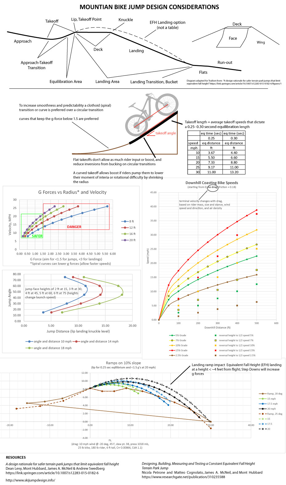
Important Words on Transitions to the Lip
There are MANY flavors of jumps, but they come down to two types, one that is planar or flat, that is more linear than circular, and one that has a curve or radius all the way to the lip edge.
The Plane linear type does not allow for much rider input or boost because riders can’t really pump except perhaps at the bottom when transitioning to the plane, and at the lip/edge where they can jump up off of it. Meaning they can jump or hop up, but they really can’t “boost” it like they can on a curved transition. These are safer(?) and more predictable, and the landings can be shorter, albeit not necessarily short. They still depend on rider input, but the variation is not as large or unpredictable. Ski and snowboard jumps are often like this, a curved entry into a long plane takeoff. However, they usually require a significant amount of soil as compared to curved transitions to the lip.
The arched or curved types come in an large range of possibilities, not one plane, flat. Flat or curved, the transition to the lip is key. Curved lips can have a circular or elliptical radius or arc of a nearly infinite range. The preferred arc is a “clothoid” (again see the PDFs). Circular curves can be pumped and boosted beyond what the calculator calculations might predict. Riders may be able to manipulate the parabolic arc of flight more easily, creating their own flow (within the bounds of our natural Laws of course). Softer curves are harder to boost, but safer and more flowy.
The Clothoid
Circles are not ideal transitions for jumps. The clothoid (or Cornu or Euler’s Spiral) is best, so is a flat/linear take off with about 0.25 seconds of time x the take off speed, typically a flat/ish segment with little to no curve. So at 15 mph (6.7 m/s) x0.25 seconds the flat spot will be 1.6 m or 5.2 ft. This means higher and longer jumps, even for small ones, or jumps with low angles (sub 30 degrees). The clothoid shape minimizes jerk or buck stress on riders from the curvature of the ramp, and their speed. Gravity slows them down as they climb to the lip, and they can simultaneously speed up relative to the curve, especially on a sharper radius or curve as they increase or preserve angular momentum. A clothoid radius is not constant, but variable along its length, the curvature at any point along the clothoid is equal to its arc length (measured from the origin). See the landing pdfs below for more information. Also see the spiral turn videos on the turn design page for spiral clothoid-like arcs. The arc of a clothoid lip is somewhat similar.
Transition G Forces
If they are circular…

^As you can see tighter transitions and higher speeds don’t mix well.
Bigger circular transitions are less jerky, a clothoid even less so. The time spent on a clothoid to the lip is nearly double that of an equivalent circular arc, thus its a smoother tranny. The minimum radius should be related to the speeds typically experienced going up the lip to limit the Gs to 1.5gs, and about 3gs max on the landings or riders will feel jerky transitions and hard landings, not flowy ones. (r min = v^2/1.5*g or v^2/14.7m/s^2). This translates to keeping jump speeds below 16 mph with a 12 ft radius…might as well go for the softer bigger tranny. However, this number should be used to determine the correct clothoid shape. The minimum r should be multiplied by total angle that the rider will rotate in the transition from the slope of the entry to the angle of the takeoff lip. The transition length should typically be close to double what the minimum circular distance would be, which is the r min x degree change from bottom to lip x2 (r min x the downhill slope angle + lip angle).
At this time I do not know the g forces for clothoids, but a safe bet might be to consider that the time spent on a clothoid to the lip is nearly double that of an equivalent circular arc. In theory the G’s in the graph above could be nearly halved for the speeds.
For tricks, such as flips and such, a curved radius is preferable, but the amount of that curve is a little complicated and related to the speed and pumping body mechanics of the rider ascending to the lip at a given speed and number of gs from the combination of speed and curvature. Tricks can still happen off of a ramp with a nearly linear takeoff that incorporates the 0.25 second takeoff equilibration into account, but flips will be harder to accomplish.

Why do Curved Transitions to the Lip Allow Boost?

- Pumping lowers the moment of inertia (~rotational difficulty), or increases speed by reducing the the radius of the jump arc (r). I=mr^2
- By reducing Inertia by making r smaller pumping effectively increases speeds or rotation on the curve, the speed you think you know at the lip may actually be FASTER than what you might measure to calculate the jump range or height because pumping adds or boosts energy into the event.
- Boosting vs. Squashing or “racering” Jump Energy
- Boosting: riders bend at the bottom, then extend at the top (and usually the reverse on way down). They move their center of mass to the rotation axis, reducing I and increasing v, as well as the parabolic flight trajectory (at most around +/- 15%?, probably less unless really skilled…at any rate, that can change jump distances and heights…meaning a 10 foot Range may need at least another 1.5 feet and then some if the rider changes the takeoff angle, which is quite likely when boosting or “popping” off lips, especially on booters with fast approaches and tighter radii.)
- Racering or Squashing: riders suck up or effectively flatten the transition curve or r, as well as the parabolic flight trajectory, and speeds may actually be lower than measured at the lip
- Speed is a function of knee bend pump, which is enhanced or squashed down energy, that changes the r of curved transitions, much less on plane ones where riders can jump off the lip, but can’t really boost it or punch it up still higher by lowering inertia
- Also worth noting, and more than I can comment on in detail at this juncture, is that suspension can modify jump estimates. I can’t say how much at this time other than the fact that plane take offs or larger radius transitions will be more predictable. Riders might be able to get more pop or boost if the ramp is short enough as they can use shock rebound to get more pop if they and/or the ramp itself compresses (or “preloads”) the shocks then releases them at the lip.
- Something else to consider is that if riders pull up, rather than let the bike’s ghost riding parabolic trajectory float below them, they are changing the launch angle as well.
- Soft transitions or clothoids, nearly linear takeoffs that consider the 0.25 second takeoff equilibrium, and minimum radius to lower gs below 1.5 will go a long way to “better” jumps.
Bike Jump Calculator
The calculator is defunct at the moment 1/9/26 I hope to get it running again soon.
I had an issue with the plugin running the jump calculator. I really don’t know when it failed, but the plugin wrecked the site for a minute.
2026 is the 10 year anniversary of the Jump Calculator!
Though it began in 2014/15, 2016 it went live:
AND thank goodness for the WAY BACK MACHINE: https://web.archive.org/web/20160319230759/http://trailism.com/trail-science/jump-design/
Here is a temporary solution. Paths shown in meters (green and black with drag(but wind at zero mph), red and blue points in feet NOT meters.
Go to this link to change or move sliders: https://www.desmos.com/calculator/jjphayymiy
*Notes:
For a step-by-step guide on actually doing some of the math and using this calculator and more read the notes below, and go to the Jump Building Guide page.
- If you find this helpful, or not, let me know with a comment or email.
- Please kick down a donation if you found this useful, or want the Excel sheet.
- Jumping is dangerous, and may cause serious injury or death (see this)
- Build and jump at your own risk, no guarantees are promised by the numbers output by the ramp calculator or spreadsheet, but they can get you in the ball park (if you know what average launch speeds will be– don’t forget speeds will slow as you climb up ramp, and drag friction will reduce R, sometimes significantly, leaving you short). Speeds can also increase if transitions are pumped, see this.
- Read #3 and 4 again, then this: THIS CALCULATOR ASSUMES same launch and landing height! (see black and red diagram). **”Jump angle” or θ = the angle of the bike the instant the back tire leaves the ramp, which should be very close to the wheel base angle when the front tire is at the lip.
- IMPORTANT: the bike jump calculator is for a “point” of mass. In turn, R will have to be shortened by: (wheelbase in feet or meters) x sin(jump angle) = distance to shorten R. For example, perhaps err for extra large 29er wheelbases that are somewhere around 46 inches: 46in/12in/ft= 3.83 ft, meaning 3.83 feet x sin(jump angle) = distance to shorten R for XL 29ers with 46 inch wheelbases.
- ALSO: What shape are you making?
- Please read and understand this.
- Launch and landing speeds will be the same (or negligibly different) if the launch and landing heights are the same (also see 5).
- For a slower/softer landing, landing ramps can be elevated, but this will change the range, R, to a shorter distance. If landing at a lower height than takeoff then R, or the the landing lip, can be pushed farther from the takeoff lip. Please see the “safer jump” pdf documents linked below for details about the best landing ramp design.
- WIND and rider behaviors like pumping, lifting, braking, spinning, flipping etc. could change any of the variables (h, R, t, and the angle of launch)– in other words the parabolic line of flight as as depicted in the red and black image will be altered, altering R
- Wind and drag may become a factor if strong enough or H and/or R is great enough
- The calculator above is for RIGID forks AND RIGID tails, i.e. hard-tails. Suspension can change the angle of launch, thus H and R. Recoil may also affect the outcome.
- Test your creation and measure carefully. How fast were you going, what exactly is the lip angle, and did you pull up or pump? Was it windy? What tire pressure and how knobby? Adjust your creation accordingly, perhaps with a correction coefficient.
- Use a level or other means to check angles (see image below).

“How do I know my speed at takeoff?” A bike computer or gps unit could work, but may not be exact, or to state the obvious, are dangerous to look at on takeoff; of course the jump could be bypassed or skipped to get the approximate speed the jump will be hit. Speed loss to gravity will occur when ascending to the lip. If high enough the loss could be significant. Someone could help with a tape measure and stop watch as well, and this method may be better than the computer, but several trials may have to be done to determine the speed more accurately, or to get an average in case the time keeper doesn’t hit the start and stop at exactly the right moment. A radar gun, or triggers, or lasers and an arduino could work too. Most cheaper radar guns might not be accurate enough near 10 mph, and usually have +/-1-2 mph accuracy issues. The Speedclock app is pretty good once you know how to use it. SeeLevel or other inclinometers and a digital level may help as well.
GOOD LUCK. HAVE FUN. BE SAFE.
*props to Greg from dirtycentury for helping with the script
Resources
- Ramp/Jump Physics (applied math) PDFs:
- Safer-jumps that-limit-equivalent- fall-height
- A design rationale for safer terrain park jumps that limit equivalent fall height
- SAFER-JUMPS-DESIGN-OF LANDING-SURFACES-AND-IN-RUN-TRANSITIONS
- Jump-Landing-Design-Limits-Normal-Impact-Velocity
- Ski jumps are not necessarily bike jumps, but for flips and such it may be best to go with these standards though the landing ramp may be a different setup: International Ski Federation (FIS) Freestyle Committee Aerial Site Specifications (note the continuous curved transition)
- Equivalent Fall Height
- other info: here, and here
- also see this:
- https://timing.microgate.it/en/products
- https://www.hbm.com/en/2232/somat-edaqlite-simultaneous-high-level-layer-elhls/
- Contact me about consulting
- A downloadable spreadsheet is forthcoming
Pingback: Trail Turn and Switchback Design | Trailism
Pingback: Trail Turn and Switchback Design | Trailism