“Give me a place to stand on, and I will move the Earth.” Archimedes
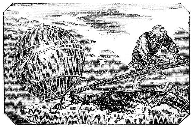
While it’s not likely that Archimedes “invented” the lever, according to Plutarch he did help fashion block and tackle for lifting items into boats. If we don’t have excavators or helicopters, levers and block/tackle are still how we move heavy items on trails today, and I imagine into the future as well.
ROCK BARS
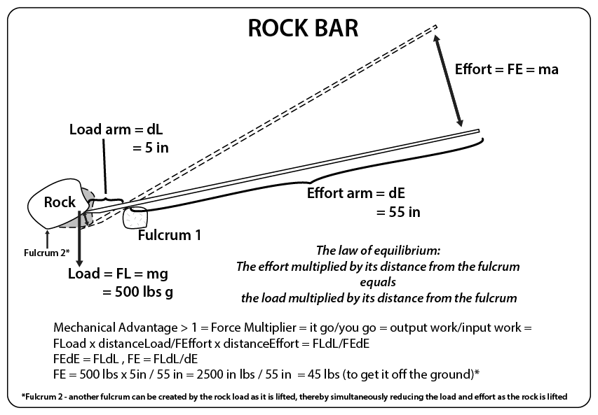
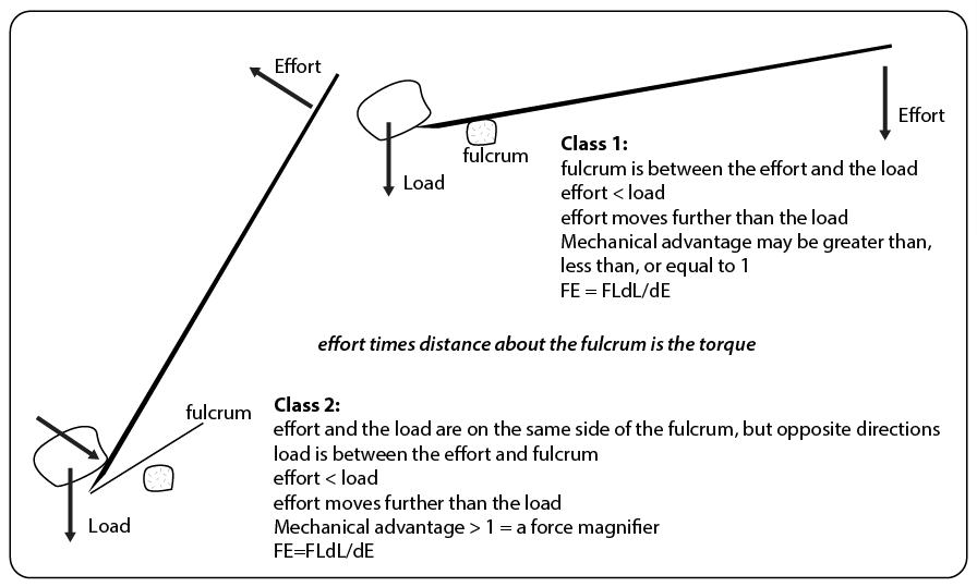
When did the advantage of using a lever first become apparent? Was the knowledge handed down by word, until finally written? I’m not sure, but rock bars are a staple tool for leveraging advantage for trail work in rocky areas. As shown in the image below, the ratio of the load arm to effort arm determines advantage, the most advantage being achieved from using the shortest load arm length practicable, or conversely the longest effort arm.
DRAGGING ROCKS WITH A GRIP HOIST
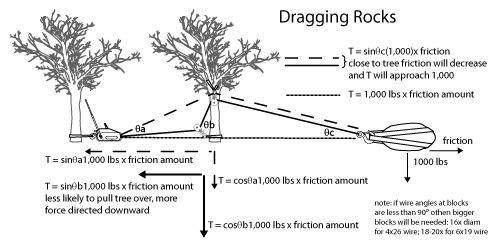
Straight/direct or directional pulls, dragging rocks, and perhaps assisting with rock bars, is often easier than rock bars alone, though sometimes quite destructive as most things in the way get plowed under. Adding a block to get lift can significantly increase the ease of a pull as friction and tensions are reduced.
MORE ADVANTAGE

2, 3, and 4 times easier, but with 2, 3, and 4 times the strokes to move the same distance as a direct or directional pull
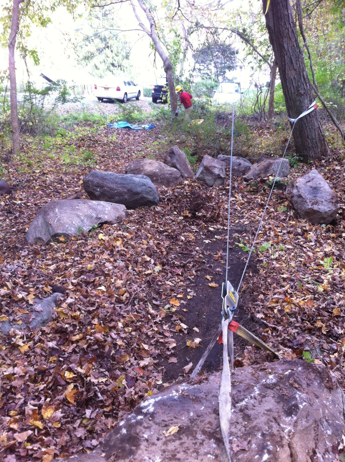
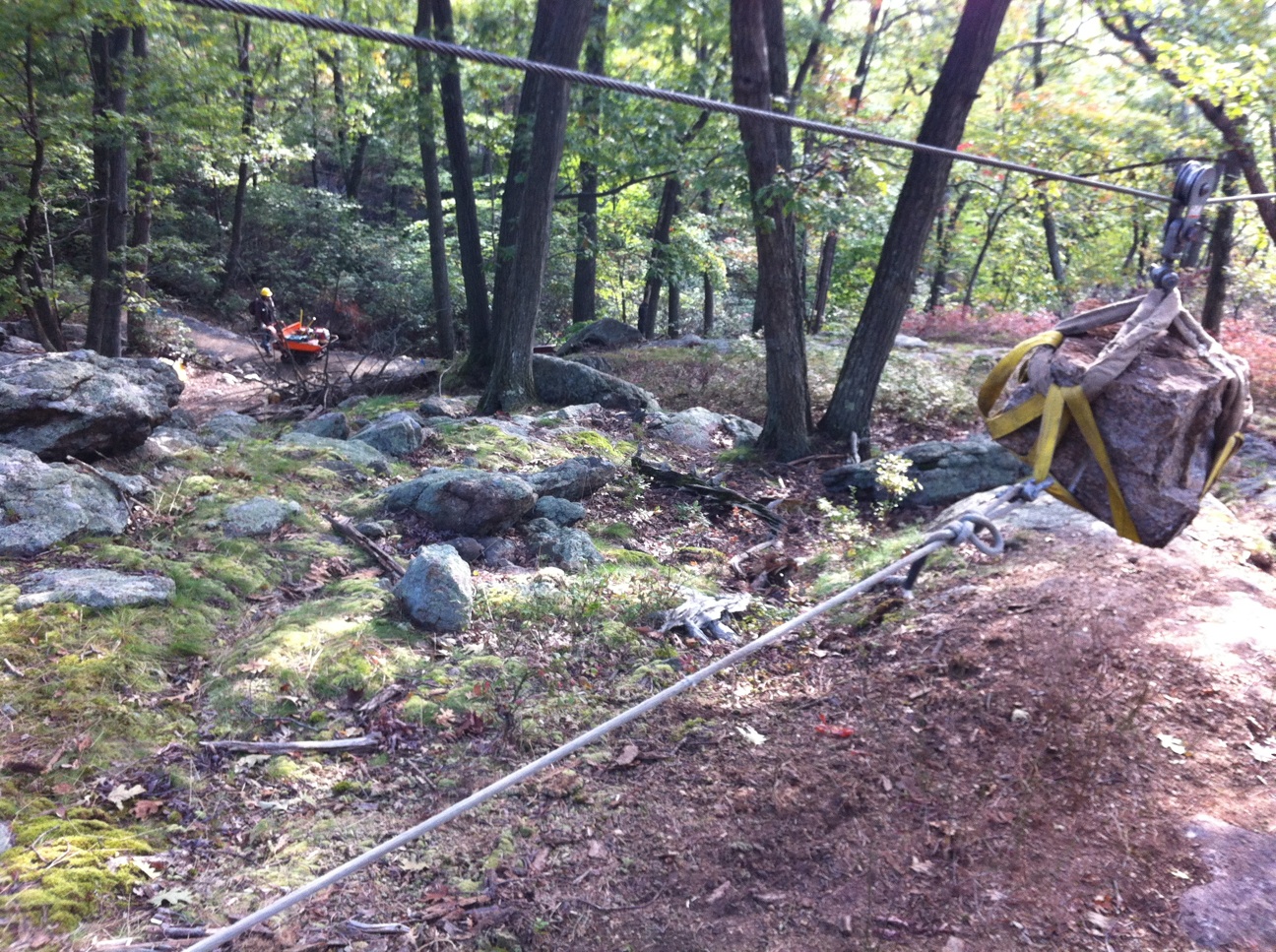
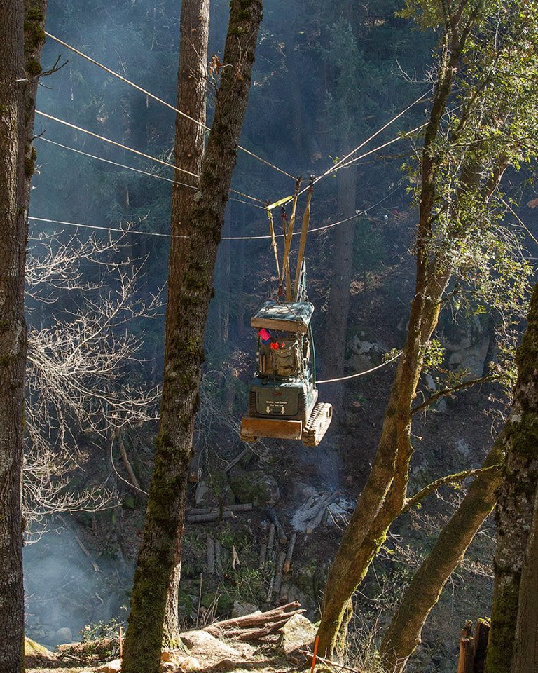
HIGH LINES or TRAMWAYS
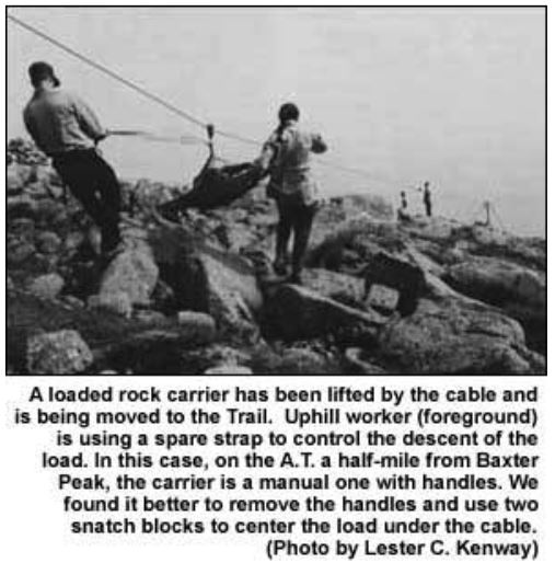
Using high lines for trail work seems to have started with Lester Kenway in Maine, as way to move rocks far and fast without damaging sensitive habitat; and as means to not move rocks with rock bars. Lester wrote an article titled “New Rock-Moving Method Saves Fragile Terrain (Tramway System Used by Katahdin Crew),” which appeared in The Register (Appalachian Trail), Vol.13, No.2, April 1990 (original article).
My first experience with high lines was with Bellfree contractors when building steps for the Sea Dahlia trail in Palos Verdes, CA.
It was Lester though, who came for an SCA and Americorps training at the Welch Trail Education Center that really pushed me to explore high lines in greater detail. He also repeated the Archimedes ditty at the top of this page to us. Lester left enough information to inform, and enough to push me to go much deeper into the physics than most workshop participants would have the patience for.
I created this rigging handbook for the NYNJTC designed exclusively for trail work with Ama Koenigshof, a protege of Lester’s. The handbook contains everything I would post on this page. Rather than write it twice, I suggest a look at the handbook.
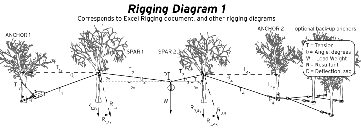
If you’ve seen my jump design and turn design calculators it’s obvious I like to apply physics and math to trail work, i.e. trail “science.” Perhaps my greatest accomplishment in understanding rigging use for trails was the eureka moment I had when laboring over this Excel Spreadsheet for the physics and safety limits of high lines: Rigging-for-trails-math-Excel. It was a work in progress in 2015.
This older version needs updating, as it assumes VERY rusty pulleys, if not clamps, not pulleys: old version. What you see in the new spreadsheet began simply enough, but snowballed into something complicated, yet practical and useful for those wanting to use high lines to move rocks, and other heavy items.
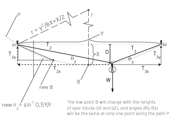
Perhaps the only thing I have not explained in full in the handbook and spreadsheet is this little item, the Sagitta:The Sagitta is what caused the snowball to initially roll, though it turns out that I should have been thinking ellipse instead of circle…long story. Lester had talked about tensions, and even had a Dynamometer, but I failed to understand how tension could stay the same during the entire trip as the line angles would change, and therefore the tensions. I hypothesized the tensions would have to be unequal, except for the lowest point along the path, when both angles were the same (assuming the same block height), which is what Lester showed us on paper. He was right, I was mistaken…sort of. They would change, but not on each side of the fly block pulley. Turns out pulleys ‘equalize’ the tensions so they are the same throughout the fly line, but still, changing angles would change tensions.
Realizing the missing information, I knew I needed to determine the arc of travel, which at first I didn’t know existed, or how to figure out. The challenge led me to use the stagitta, and in turn create the spreadsheet. I finally fully grasped the inner workings of high line physics…well at least as far as I wished to take it, but it was pretty far considering that I started with almost nothing and had to do a lot of research and deduction to arrive at the answers, and beauty of balanced equations….and then Wayne contacted me and the ball deflated, got patched, and started rolling again, but not without some resistance from me. Wayne pushed me in a new, correct direction, but there were a number of unknowns to still discover. Wayne thought I could help him with high line problems he was trying to solve, but first I had to leave the rust behind, so to speak, and rethink the variables involved in flying objects on high lines. The new spreadsheet is just that.
^image from from Peter Jensen, courtesy of Eddie Walsh of Tahawus Trails
Sheave size
- ANSI B30.5 (required by OSHA regulations as printed in Federal Register on 6/24 and 27, 1974) SAFETY STANDARD FOR CABLEWAYS, CRANES, DERRICKS, HOISTS, HOOKS, JACKS, AND SLINGS
- 5-1.7.5 Sheave Size: (c) Load block (lower) sheaves shall have pitch diameters not less than 16 times the nominal diameter of the rope used. [16:1 16 pitch diam to 1 rope diameter]
- This 16:1 holds for acute angles, or really 180 degree turns
- As seen below, the strength declines with bends. It is down 10% (or to 90% of a straight pull) at a 16:1 ratio
- Loads should be reduced by the efficiency drop (e.g. 10% for 800 lbs max loads with a 2 ton hoist means 800-80, or 720 lbs.)
- Not that you should use a 3.5″ block with a 7/16″ rope (as it is not a 16:1 ratio), but if Ratio A (below) = 3.5/(7/16)= 8 or 83% then for a 2 ton hoist with a max load of 800 lbs (as that 800 lbs translates to 4000 lbs on the wire) the max load drops to 664 lbs.
- note that for 180 degree 2:1 pulls the stress on the block eye also doubles (see stress formula below)
- Sheave Size & Wire Rope Strength PDF
- Stress and Strain Curves
- Bending wire rope reduces its strength. To account for the effect of bend radius on wire rope strength when selecting a sheave, use the table below:
| Ratio A= sheave diam./rope diam. | Rope Strength Efficiency Compared to Catalog Strength in % |
| 40 | 95 |
| 30 | 93 |
| 20 | 91 |
| 15 | 89 |
| 10 | 86 |
| 8 | 83 |
| 6 | 79 |
| 4 | 75 |
| 2 | 65 |
| 1 | 50 |
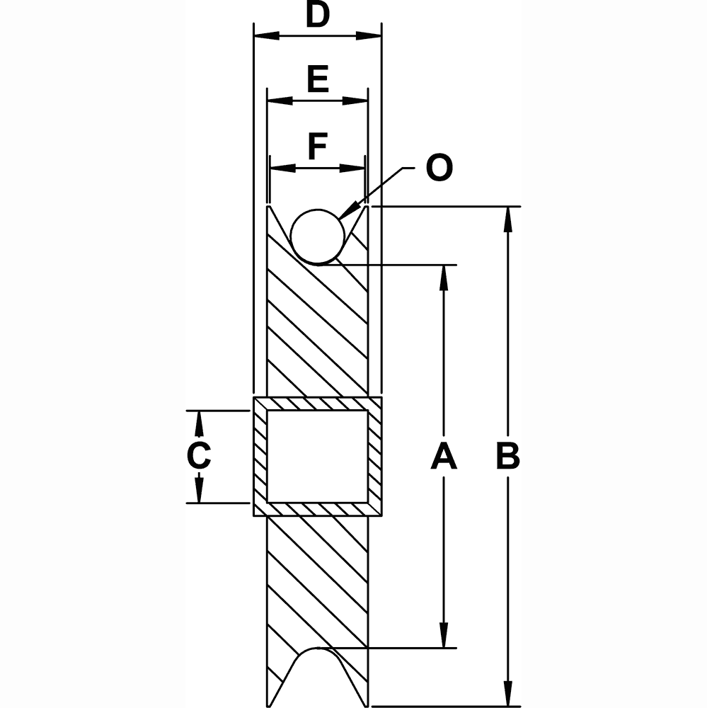
| A | Pitch Diameter |
| B | Sheave Diameter |
| C | Bushing Inside Diameter |
| D | Bushing Width |
| E | Sheave Outside Width |
| F | Sheave Inside Width |
| O | Cable Size |
- tech bulletins
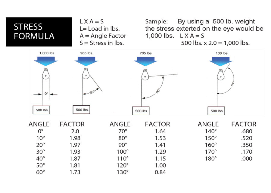
- Work Load / Stress Formula / Load Calculation:
- The safe working load limit (mechanical advantage) is the maximum load in pounds which should ever be applied, and when the load is applied uniformly and in direct tension to a straight segment of wire rope. By changing the degree of angle between lead and load angle, this also affects the stress on the block. The stress on the eye may be decreased by increasing the angle between the load and the lead angle. See chart and illustration below.
- Stress Formula: (L x A = S)
- Load in pounds (L) multiplied by the Angle of pull (A) equals the stress generated in lbs on the Block (S)
- Safe Work Load Limit: This is the maximum load (in lbs.) which can be applied to the Block and which has been established (Load Capacity)
Belaying
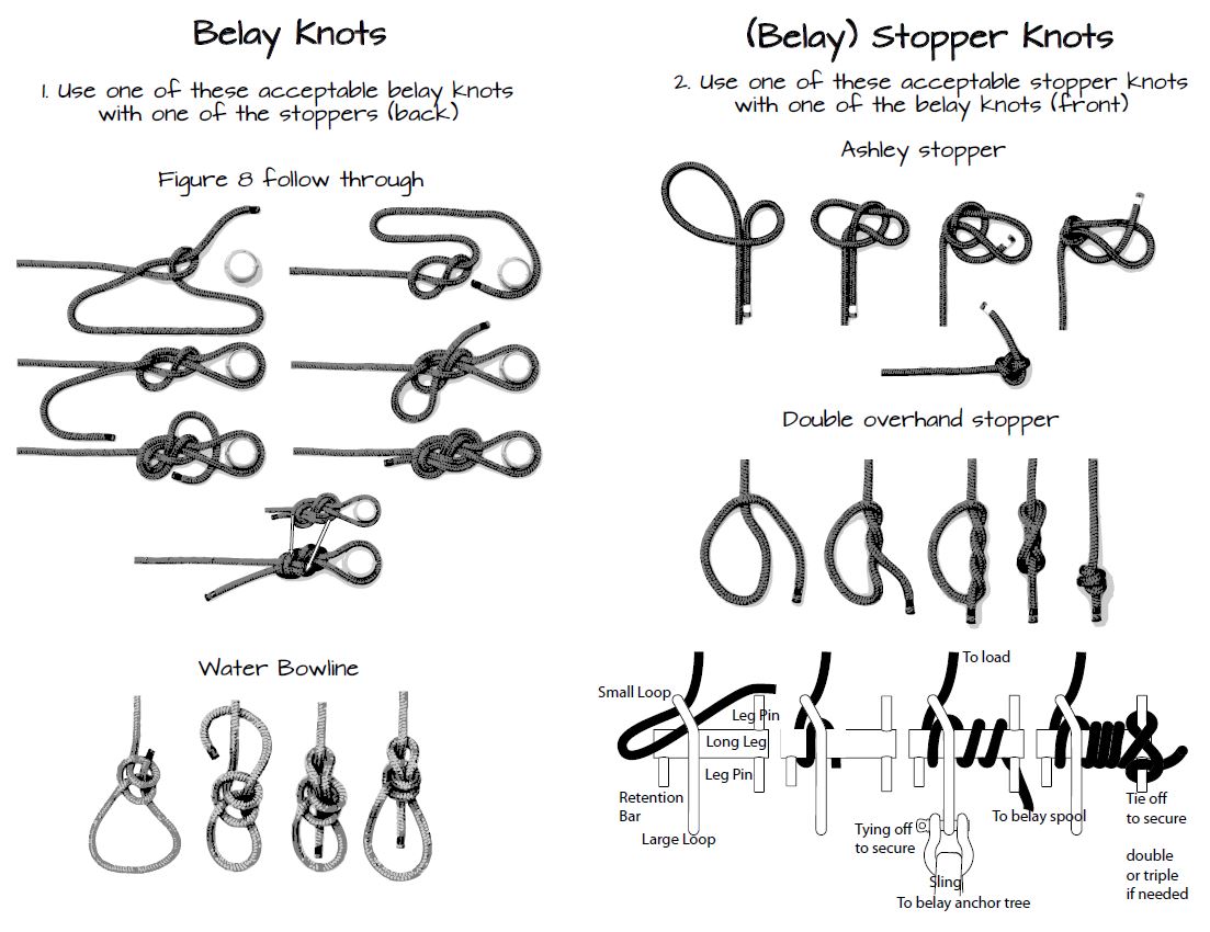
PDF of image above: link
Belaying a big rock on a steep slope, no Portawrap
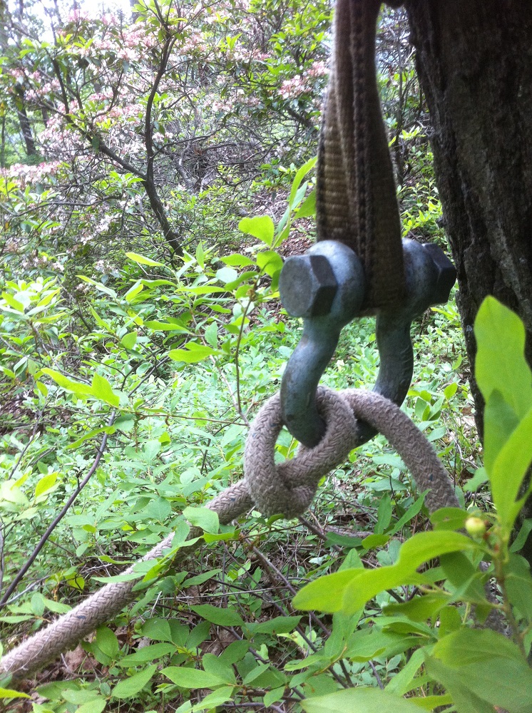
The big rock in the images below was moved with rock bars, the descent into place controlled with a belay line. At 150-175 lbs/ft3 the rock is approximately 3x3x1.5= 13.5ft3x165= 1220 lbs.
More rigging manuals:
- ISHA Hoisting and Rigging Safety Manual PDF
- Hoisting and Rigging Fundamentals for Riggers and Operators PDF
- FEMA Lifting and Rigging Manual PDF
I don’t know what more I can say here in regards to high lines, as the handbook and spreadsheet do most of the explaining. Enjoy, be safe, and you are welcome.