What’s the best turn design for a trail segment? Just what the “perfect” design arc or angle and possible in-slope is for a trail turn is part personal preference, and sometimes part science/math… and maybe some psychology. It’s not that this can’t be answered, though more rhetorical than absolute, turn design depends on the user groups, safety, and long term sustainability of the segment.
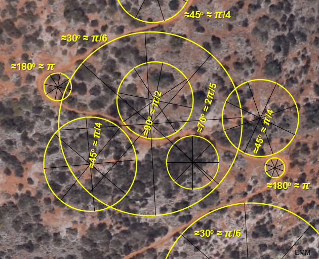
some are most likely spiral or logarithmic,
but it does make a (round) point
Walking, riding, or running, some turns are just awesome, others, not so much. Just how tight “should” a directional change be for the best flow of water and users often boils down to the steepness of the hill or mountainside, the trail grade, not to mention trees, rocks, and those trees and rocks acting as anchors for the turn. The feel is related to the speed at which users enter and exit the turn, and the general setting of the turning area.
For bikes, speeds can be controlled with slopes preceding turns to slow bikes down to the speed desired, or to give them a kick and more G’s with a downhill beforehand. Switches or turns that changes direction by 180 degrees or so vary with user groups. Should a bank (or in-slope) be added to a turn? How steep? A wall? Do you want or need a bank or berm? Some of these questions are explored here and the links below.
Banks
To bank or not to bank? That’s a personal question. Will the bank be… an in slope, in-slope, or inslope? That answer is not in a dictionary yet (as of 2022). According to the AP and the CMS (Chicago Manual of Style) use two words, in slope. However, “in-slope turn” or “in-sloped trail” are compound adjectives modifying the word after, so use the hyphen. Further, “in” usually means “not,” so would we ever use “inslope” as that form means unsloped, bad choice. Like the English language, turns with or without banks have some gray zones and local dialects or best practices, and maybe no “rules,” but keeping users going in the right direction as intended may require a trip to a bank.
bank (n.2)“natural earthen incline bordering a body of water,” c. 1200, from a Scandinavian source such as Old Norse *banki, Old Danish banke “sandbank,” from Proto-Germanic *bankon “slope,” cognate with *bankiz “shelf” (see bench (n.)). As “rising ground in a sea or rover, shoal,” from c. 1600. As “bench for rowers in an ancient galley,” 1590s. There probably was an Old English cognate but it is not attested in surviving documents. The nasalized form likely is a variant of Old Norse bakki “(river) bank, ridge, mound; cloud bank,” cognate with Swedish backe, Danish bakke “hill, rising ground.”
bank (v.2)
1580s, “to form a bank or slope or rise,” from bank (n.2). Meaning “to rise in banks” is by 1870. That of “to ascend,” as of an incline, is from 1892. In aeronautics, from 1911.
berm (n.)“narrow ledge,” 1729, from French berme (17c.), from Old Dutch baerm “edge of a dike,” which is probably related to brim (q.v.). In U.S., especially “grass strip beside a road,” originally the name for the bank of a canal opposite the tow path (1833; berm-bank is from 1832).
etymonline [sensible and neat that “bench” is related, and “banks” are dirt savings storage areas that take some investment]
Because we move on trails the First Law of Motion applies: users will continue in a straight line unless acted upon by a force– and the faster an object goes the harder it is to turn from that straight line, it takes more force. Banks can add a force against users and direct or redirect them, but just how steep the banking should be changes with trail users, soils, and weather. The faster tires, paws, hooves, and feet travel, the more likely they will slide around a corner. The sliding is caused in part by the fact that to stay upright at higher speeds or tighter turn radii, the more we have to lean. The lean means feet and wheel move away from perpendicular contact, reducing the friction at contact points that help keep users in place. We can meet that lean angle with an in sloped turn or bank.
As we see in the equation below (and the turn and switchback calculator), a bank can make turn tightness irrelevant to a point. Some turns are cut or lifted a priori, some a posteriori, to make a tight turn work without slipping. For hiking only switchbacks things could be different, or more forgiving, but the feel or “flow” of the trail for a walker and water still matter, and take some planning for the design outcome.
 conic section |  involute |  conru spiral (clothoid) |
Bank angles and the number of arc degrees can be determined by the landscape, and/or intuitions or feel and eye based on previous experiences (or not). Circular banks and radii can be determined by plugging numbers into variables and solving for what designers need: rg tan ø = v2 (r= arc radius g= 9.8 m/s2 v=velocity ø= in-slope angle).
Regardless of curve shape, the tighter the arc and/or higher the velocity of a user, the steeper the in-slope bank should be, and the more G’s that will be generated on the user (see below). This seems intuitive or makes common sense, but the equation for circles above spells it out. Interestingly enough, this equation and others often used for motion is a case where mass is irrelevant! Friction is not, but masses cancel: centripetal force, Fc = mv2/r = μsmg cosø + mg sinø; centripetal acceleration: ac = v2/r… g force is the extra weight from acceleration around a circle or v2/rg.
Bikes and runners
Turns are probably the easiest way to slow down bikes and trail runners, but how many and how sharp or hard the turns are is a question that is beyond the scope of this discussion, but not something that should be taken lightly. Subtle curves are usually a function of the landscape or slope as well as immovable objects like rock and trees. The same could be said for hard turns or strong directional shifts, some with blind spots, but typically hard turns are a manufactured necessity with many possible reasons (including none) to justify their existence.
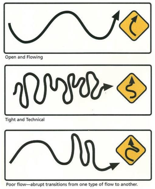
These aren’t turns as much as layouts, but they might illustrate part of the possibility of the turn character on those layouts (source)
As far as bikes are concerned, head tube angles and wheel bases will change how bikes handle turns. While this is being written most XC bikes are near 70+ degrees and most DH/FR bikes around 65. The latter is more stable, but not great at tight turns because the slacker angle increases the wheelbase. The benefit though is more stability in rough terrain, but harder recovery if knocked off-course— perhaps offset by more suspension travel. Take home lesson here: turns should be more drawn out for FR/DH speeds, but this is sensible and insensible as speeds are generally higher as well. How fast is too fast if trees will be hit that could kill or maim riders? I can’t answer that, but turns can if desired. Besides that hard turns can almost feel “unnatural” if not executed well.
When will a bike or runner slide? This is relative to the tire or shoe and friction coefficients, as well as the arc or radius of the turn, whether it is in-sloped (and how much), and again the speed of the bike or runner around the turn and the behavior of their bodies, including the feedback they get from the turn and possibly in slope (no modifying, no hyphen, but what is an in slope if not a modification?).
Look Closely
Is there a berm forming on a once nearly flat turn that feels or works fine with its new body shaped by users? What are the user groups and average speeds? How consolidated or firm vs. loose is the new berm body bump? Building in that area again, let the users make them or prefabricate something close to the one made by users already. If firm then the user-created slope is probably steep enough, if loose then perhaps the soil not ideal, the berm is still young, or the turn is too tight and hasn’t settled into an appropriate shape yet. Motorcycles can help make fast work of the process, or speed up geology and the anthropomorphic morphs we call berms or banks.
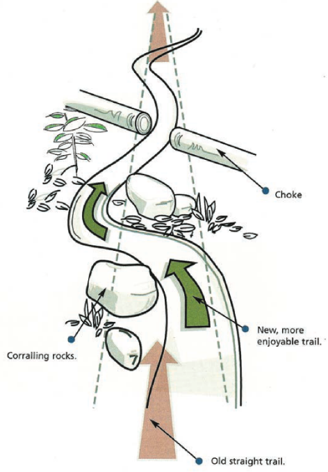
Cutting inefficient turns
Efficiency is one of the hardest trail design aspects to nail on sinuous layouts. The straightest distance between two points is a straight line, and if the turn is inefficient and not discovered or hammered out in the design and build phase, the turn will be cut or straightened out by Newton and/or impatience and there’s not much you can do other than learn from your mistakes by coming up with a solution. The users usually win, so you might want to opt for those consultants.
Chokes
Turns help slow bikes down and can add character or flow. Chokes can help, but can be difficult to pull off. The best thing to keep in mind is if the trail, now choked, is still straight or now has actual turns in it post choking. The idea being to move away from Newton’s first law and force riders to the second… maybe? It’s easy to stay straight and maintain speed, adding turns can change or choke speeds and directions, with direction in the form of deflections.
Switchbacks
Bikes have certainly pushed trail building in new directions when it comes to obtuse and acute turns and 180 degree switchbacks, but there are some lessons to be learned studying the basics of switchback design.
| Drawing | |
|---|---|
| Type 1: Radius Switchback | Preview |
| Type 2: Circular Landing Switchback | Preview |
| Type 3: Rectangular Landing Switchback | Preview |
| Climbing Turn | Preview |
An “old-school” video, but cool on many levels:
Direct me
What “should” a turn arc be? And if in sloped or banked, how many degrees?
- The turn radius depends on the speed of riders or runners
- The radius can be very tight: if the in-slope (and less-so the height) is changed (and speeds are slow)
- As a general rule, consider this:
- A 10 mph turn speed (should be slower for blind turns, but there should be “no” blind hard turns on two way trails)
- No bank (no in-slope)
- No sliding/slipping around the turn
- A coefficient of friction of 0.5 (“dirt”, unconfirmed value)
- This coefficient of static friction changes with soil type/conditions, tire inflation, and tire selection. 0.5 is a ballpark average. If slippery or packed decrease to 0.3 or 0.4, if tacky or loose increase 0.6 or 0.8. You can determine the coefficient of static friction by this experiment: **below
- Do the trails often get icy? the coefficient of static friction is closer to 0.1
- The Crr, coefficient of rolling resistance, kinetic friction μk: how to pdf | reprinted below near the bottom of the page
- The turn radius with no berm should be: ~13 feet at ~10 mph
- At 15 mph with no in slope and a 0.5 coefficient of friction the radius for no slipping needs to increase to about 30 ft!
- Add a 10% in-slope to the turn and the 15 mph radius of 30 ft can be cut down to 20 ft or 17 ft at 15% in-slope
- Use the turn/switchback calculator below to play with the turn radius and angles (for multi-use trails I’d personally recommend not exceeding 20% in-slopes (unless there is a low bottom walking lane at a reasonable in slope), 3 feet high banks, or turns less than 9 ft radius. Hard turns or switchbacks might need a second line to accommodate different user groups and efficiency issues. Most bikes will do fine at sub 15 mph with a 16 ft radius 180 degree turn. More is preferred, although bigger turns can become a drainage, rut, and user conflict problem if lines of sight are poor. Correctly designed turns can control speeds to some degree, or depending on how many degrees, eliminate a user-created demise of the turn.
Some of the tables and graphs below might help get you closer or assist with thinking about how circles and turn speeds relate. Ultimately lots of time riding and experiencing turns helps if building bike turns. Running is easy and can help with most layout applications for slow multi use turns.
Determining the coefficient of static friction
- The angle at which objects start to slip on the dirt is directly related to the coefficient of friction of the said material- dirt, rock, wood…
- For the static friction test the tires should be put on the native dirt being used (compacted) and then the dirt would have to be tilted until the tire slides.
- Build a 4 foot arc from 0% up to nearly vertical, and place the bike upright at higher and higher points until it slides
- It will slide when when the component of gravity exceeds the maximum value of the force of static friction.
- The coefficient of static friction is equal to the tangent of the angle at which the tire slides. fs = fs max = μs N or μs = F/N or sin(ø)/cos(ø)=tan(ø)=μs
- A similar method can be used to measure kinetic friction μk.
- Give the bike a push downward as you increase the angle
- When the bike slides with constant velocity, the tangent of that angle is equal to μk.
- You would need ramps of varying angles, not arcs for this.
- More simply, you could just attempt to turn on an open flat section of the same dirt at different speeds until you begin to slide. Measure your turn arc radius with a string by moving the center point away from the arc until the arc of the string matches your actual arc on the ground. Then plug that radius into the calculator’s radius as a starting point. Or just do complete circles or donuts and half the diameter. Chances are they will NOT be perfect circles, but spirals or clothoids that change the radius as you move. See the videos below.
- Determining the Crr, coefficient of rolling resistance, kinetic friction μk is also important: how to pdf | reprinted below
Determining a bike’s turning arc, and turn arcs for trails in the real world with or without a calculator
You could skip 1-3 below if you do circles in the dirt (or asphalt), as the donuts you make will give you the arc, or diameter (and radius) of the turn at the speed you make the circles or turn. Try doing faster circles or turns, and the arcs will get bigger. You now have a starting radius minimum. Err on going bigger, and use the calculator if you want for plans to use banks. FYI, a really tight bike turn (wheelbase 45″) at about 5 mph has a 9 ft radius.
The dynamics and variables change on inclined or sloped turns.
- Determine your bike’s steering wheel angle at full left or right—ride your bike on the street and make some sharp turns at slow speeds…or better yet, try to do a complete circle. Note the position of your bars relative to the top-tube. Measure with a protractor or speed square.
- Subtract the turning angle from 90 and find sine for that angle.
- Divide your wheelbase, in inches, by the sine value from Step 2, and multiply that number by two to get the turning circle diameter, in inches. Divide by 12 to get feet.
more info: mechanics/banked_with_friction
Front Versus Rear Wheel Turn Radii
The rear wheel of a bike has a smaller turn radius than the front wheel. The smaller the radius of a turn, the greater the difference between the front and rear wheel travel paths.
It fascinates me that we are so adept at making nearly instantaneous decisions at high speeds on where we need to set up our front wheel as to avoid clocking our rear wheel when approaching and passing an obstacle. I assume it’s a function of rewards and consequences. How wide is that difference?


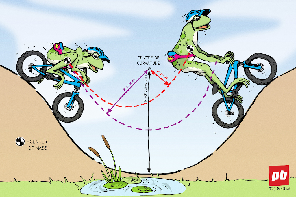
Pumping A Turn
Curves on pump track rollers, jump or vert transitions, and even turns or berms are where, or how, speed can be generated (or lost). Additional speed (acceleration) from a pump is based on changing radii. Pumping lowers the moment of inertia (~rotational difficulty), or increases speed by reducing the the radius of the berm arc (r). I=mr^2. For example, a radius of 8 feet can shrink to 7.5 if a rider extends 1/2 foot standing during a pump to get closer to the center of the curvature (or rotation) of the berm or roller. Speed can be increased around a turn when the radius shrinks from standing/pumping while turning.

Clothoids probably make better turns, or safer ones with less body stress from g’s, but the math in the above table estimates are for circular berms (or jump radii) as a means to show differences gained from pumping (ignoring friction and drag). The pumping motion might be a clothoid/spiral shape around a circular berm or transition because riders are moving forward as they incrementally pump up and down, or with the right body mechanics more circular pumps could generate more speed. The table above is graphed in two ways below.
same pump concept and result
As illustrated above (and below), riders don’t necessarily travel/trace a circular path on a circular radius berm when they rail it. Depending on how they enter and exit the berm, scale the face, and roll possible entry/exit rollers, their path of travel might be closer to a spiral path so perhaps building a circular berm is fine if riders are tracing out spirals. I hope to study or investigate these hypotheses and the estimates in the table above. There is a point where larger radius turns won’t return a boost depending on speeds as the radius and velocity are what give the potential to add speed and change the g forces. Also how efficient and strong the pump is executed as well the height and speed of the rider. I think the applications are most relevant for pump tracks and BMX or dirt jump trails. For that application or out in the back 40 if the berm is long and flat enough the Crr will certainly come into play. Need to add some speed to a flat area with some “turnage”? Turn it up and pump side to side, w00t! (entry and exit rollers may or may not be necessary)
One way to add speed to a pump track is with tighter circular radii, but the extra g forces can be dangerous, and lead to knee problems and more. Be careful what runway speeds might be coming into a berm or things could get ugly in the approaching circular berm or circular jump face.


When I was kid I rode the The Lochness Monster roller coaster in Williamsburg, Virginia, which employed two clothoid loops rather than circular loops. Clothoids require less entry speed to complete the loop and subject riders to fewer G’s because of the slower speed and progressive spiral turn of the loop entry and exit. In the same manner, and perhaps a conjecture on my part at this time, a clothoid berm “might” indeed require less entry speed to be faster than a circle berm, and will better match the clothoid shape riders make when they pump, increasing speeds beyond what they might get from a circular berm alone on exit. Clothoid jumps are typically “best,” why not the same for (some) turns? Choose carefully.
Curve setting out by perpendicular offsets from tangent lines
I built a spiral curve combining two different radii based on the Golden Ratio. That was relatively simple compared to setting curves using tangents while considering rider speeds. Clothoid alignments are a little more complicated than whipping out a string and making part circles.
Make it fit
Can’t fit a round berm in a square plot? As mentioned in the spiral curve post link above, and evident from the drawing below, one of the things a spiral can do that a circle isn’t, is to flatten the depth needed to make your turn fit between trees and such, but still give it the same entry and exit point. You’re welcome.

Step-by-step rolldown test:
- Determine Crrg (how to pdf; how not to web page)
- Drive at a steady low speed, and start timing the moment you take your foot off the electrons.
- Stop timing as soon as you come to a stop.
- vstart is your starting speed and t is the time it took to roll to a stop.
- Do a few tests at different low speeds and take the ratios vstart/t. They should be the same if you are starting slow enough. This is the value of Crrg. Also try both directions and average (to eliminate any small slope).
- If you don’t trust your speedometer you can measure roll-down distance d and time t, with Crrg=2d/t^2 (still at low speeds). I am using mks units on my charts so take care accordingly (velocity vstart in m/s).
- If you suspect some nonlinear effect near stopping, you can measure the acceleration at slow speeds but away from 0.
- For example, if you measure the time to go from 10km/hr to 5km/hr, then Crrg= deceleration = Δv/t = (10km/hr-5km/hr) / time. Remember to use consistent units. If you also don’t have a reliable speedometer at low speeds you can use measurement of time and distance only. Put three marks on the ground at some distance you can coast at low speeds, eg at 0m, 10m, and 15m. Measure the time t1 to coast from 1st to 2nd mark and the total time t2 to coast (on the same run – use the ‘lap’feature of your stopwatch) from 1st (not 2nd) to 3rd mark, and the corresponding distances x1 and x2.from 1st to 2nd and from 1st to 3rd marks. The acceleration experienced is
- Crrg=2/t2-t1(x2/t2-x1/t1)
- Determine ρCdA/2m
- Now do a test with high starting speed (where wind resistance is important, e.g. above 70km/hr, 43 mph).
- We have to solve Vstart = sqr root a/b = tan (change in time times sqr root a/b) for the unknown b(my abbreviation for ρCdA/2m), possible in several ways:
- Use the contour plots below. Each plot is for a different starting velocity (labeled at top, e.g. the first is for a vstart of 110km/hr). Find your value of Crrg on the x-axis, go up till you hit the color for your measured time, and read off the value of ρCdA/2m on the y-axis.
- Remember these are in mks units; meters/s^2 for Crrg and 1/meters for ρCdA/2m.
- You might do this at several different high speeds to get a better value. Or,
- With a calculator, guess and check values of b, or
- Use the tables at the end (for 70km/hr starting speed only).
What grade will my turn be?
Rise/Run @ Diameter vs. Rise/Run @ Circumference:

Pingback: Trail Turn and Switchback Design | Trailism
Pingback: Trail Turn and Switchback Design | Trailism